Soil – most think “hey, it’s just dirt”, but when it comes to electricity, soil becomes more complex. Electrical resistivity (resistance to current flow) is one characteristic of soil that requires specific knowledge regarding testing and application in grounding system design.
Soil is made up of combinations of clay, sand, loam, and various types of rocks. These components have differing amounts of electrical resistivity, and the soil composition varies significantly throughout the United States.
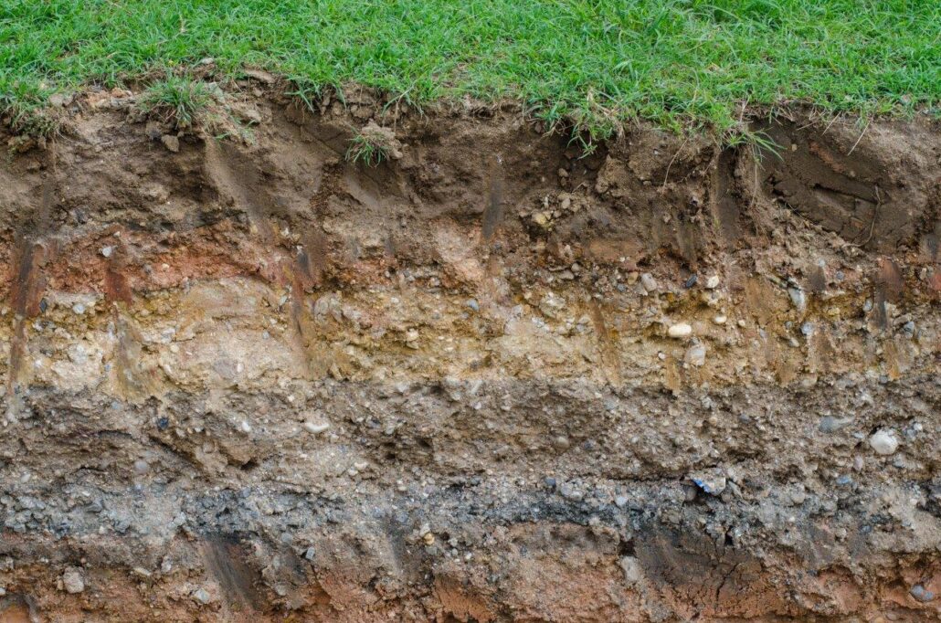
Soil is typically made up of layers and is not homogeneous.
Soil resistivity testing and the resulting measurements are the foundation of designing an effective grounding system. A properly designed and installed ground grid will be able to carry fault or lightning current safely without damaging equipment or injuring personnel. The industry standard for soil resistivity testing is IEEE Standard 81 Guide for Measuring Earth Resistivity, Ground Impedance, and Earth Surface Potentials of a Grounding System.
Several methods of soil testing can be employed prior to the design and construction of a new site, including:
- Soil Borings – These are typically used for structural/engineering purposes and create a soil disturbance. They are typically not taken deep enough to use for soil resistivity results and are not considered reliable for ground grid design.
- Three Point/Driven Rod – This measures a small volume of soil around a driven rod. It requires long rods, creates a soil disturbance, and is not very practical or reliable for soil resistivity results.
- Four Point/Schlumberger – This measures a large volume of undisturbed soil using equally spaced test probes. While the results can be useful, this method is more commonly used in the oil and gas industry, as it is able to identify vertical shelves.
- Four Point/Wenner – This is the most commonly specified test method for acquiring soil resistivity data. Like Schlumberger, it also measures a large volume of undisturbed soil by taking readings at prescribed test probe spacings that indicate, when plotted against probe spacing width, whether there are distinct layers of soil or rock, and gives an idea of their respective resistivities and depth.
Unfortunately, many testing firms are not familiar with IEEE Std 81 and the common pitfalls of soil resistivity testing. Successful test requirements include:
- Avoiding interference from nearby structures which can affect results.
a) Active interferences, including parallel transmission/distribution lines, communication circuits, and stray DC currents
b) Passive interferences, such as metallic fences, tower grounds, pole grounds, building foundations, buried conductive objects, metallic pipes, and sidewalks with rebar - Awareness of shock potential from induced voltage on test leads
- Researching the recent and long-term weather conditions. The area may be affected by drought, flooding, or temperature fluctuations.
- Familiarizing yourself with the site by studying Google Earth and planning your traverses before arriving on site. Site conditions will dictate traverse options.
- Arranging locating services prior to testing, if required by the client
- Acquiring permission to access private property, if required
- Awareness of extremely dry or high resistivity (sandy or rocky) soil that may require:
a) Extra probes at each probe location
i) We’ve used up to four 4-foot probes in a single location to increase current flow and reduce probe resistance
b) Longer probes (2-foot typically, may need 4+ feet)
c) Added water/salt to reduce the probe-to-soil resistance and increase current flow
i) Specifications frequently say this is not allowed, but it is often necessary to achieve enough current flow for successful testing
ii) Included/recommended in IEEE Std 81 6.2
Soil resistivity testing requires sturdy, conductive probes.
Case Studies
Below are five case studies outlining common mistakes made in soil resistivity testing. Review them to learn about the recommended best practices.
Example 1 – Not Enough Data
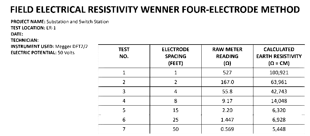 This company hired a testing firm that measured one traverse with a 50-foot maximum spacing. This is not enough data to ensure correct values and good design data. They should have done a minimum of two traverses. Many clients require two sets of perpendicular intersecting traverses (a total of four traverses). Additionally, depending on the site’s size (which was not documented in the report), larger spacings may be required. Pay attention! On this test form, the calculated soil resistivity value is in Ohm-centimeters while results are typically reported in Ohm-meters. The Mars Climate Orbiter burned up in the Martian atmosphere due to a navigation error caused by a unit conversion mistake between different teams involved in the mission. Always verify that the measured or reported units are reasonable. If they are not, the data may not be trustworthy until corrected.
Example 2 – Wrong Test Location

Another testing firm measured three traverses inside an existing plant area. Based on satellite imagery, the location of the testing and the previous structures implied that utilities were still buried in the area. The soil resistivity measurements appeared to show non-conforming data and lower than expected results for the area, likely due to conductive items in the soil where the testing was performed. Any metallic items, grounding and bonding conductors, or concrete pads will have a negative/false effect on the measured resistivity of the soil. Any fencing in the general location may also have influenced the readings. We recommended retesting away from the site.
Example 3 – Location Challenge

Another firm performed testing next to the site and along the fences. While it may seem ideal to test the soil as close to the site as possible, best practice involves avoiding testing parallel to transmission and distribution lines, as well as over pipelines or other underground utilities. We recommended the client use Google Earth and site observations and retest in locations away from buried and grounded metallic equipment.
Example 4 – Access Challenge

An existing data center planned a new building next door in place of an existing parking lot, and the electric utility required soil resistivity measurements. The closest suitable area for measurements (red arrow) was ½ mile away – not ideal, but the best that the site location and conditions would allow. Testing site access can have unique circumstances. In this case, the owner of the testing site, a mental health facility, had patient safety concerns regarding the injected current on their property. After careful explanation of our testing process, we were granted access. Be prepared to explain to a site owner what you are doing, especially when accessing private property.
Example 5 – Density Challenge
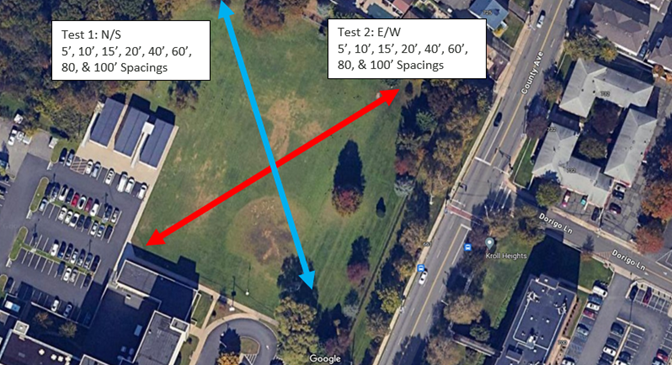
A densely developed college campus required soil resistivity data to design a new, dedicated grounding system for lab test equipment. The area next to the lab was heavily wooded and included underground utilities. Measurements taken in this area were inconsistent, making the data unreliable. The closest suitable location was a ½ mile away where two diagonal traverses were measured with 100-foot spacings. In urban and suburban areas, athletic fields, golf courses, and parks are tempting measurement sites. While these may be the best or only nearby options, watch out for buried irrigation systems, lighting circuits, and other underground objects that may influence results.
Best Practices
Plan ahead!
- Know the client specifications and IEEE Std 81 requirements.
- Know your equipment and the test process – we have seen “competent” individuals use a meter incorrectly.
- Identify traverse lengths/locations with Google Earth. When on site, adjustments may be necessary.
- Never perform only one traverse. Multiple traverses help confirm that the data is correct and identify any outlying or suspect data points.
- Pay attention to the soil type around the site through internet search, on-site observations, and a Geotech report, if available.
- Research the recent and long-term weather data for the area. Be aware if the area has experienced a drought or a recent flood.
- Request access to private property sites and “call before you dig” markings if required.
- Never leave the site without calculating and plotting the soil resistivity values. This provides a clearer understanding of what’s happening. If two traverses in the same area are drastically different, you should find another test location and attempt another traverse or two to validate the results.
- Include all this information in your report. Make sure to provide a marked-up Google Earth map showing where you measured your traverses.
Achieving outstanding results in soil resistivity testing requires prioritizing comprehensive knowledge, thorough research, and meticulous planning. These elements will lay the foundation for your success.